
Specific additional guide for preparation of technical file for electrical motors with Converter
The requirements of this guide are added to “Guideline for preparation product technical file for ATEX certification” (I-O-20)
Note: A converter is also known by other terms. For example, a frequency converter, a converter drive, an inverter drive, a variable speed drive, an adjustable speed drive (ASD), or a variable frequency drive (VFD).
Marking
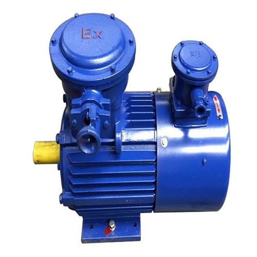
Motors that are started and operated with a converter must:
-
Include the phrase 'For Converter Operation' on a label which should be attached to them.
-
Indicate the range of speed and operating frequency of the motor.
-
Indicate the application and torque specifications.
For example: variable torque, constant torque, constant power, etc.
-
If a specific type of converter is required, its specifications must be indicated.
Instruction
The following items, in addition to other necessary standard requirements, must be included in the manual for this type of motors:
-
A speed/torque diagram.
-
For the motors with Exe protection, that have been type-tested with a converter, the converter specifications should be mentioned for comparison and selection of the appropriate converter by the user (usually presented in a table format)
-
Rated motor current
-
-
Weighted Voltage Total Harmonic Distortion (WTHD), or pulse frequency
-
DC-Link voltage
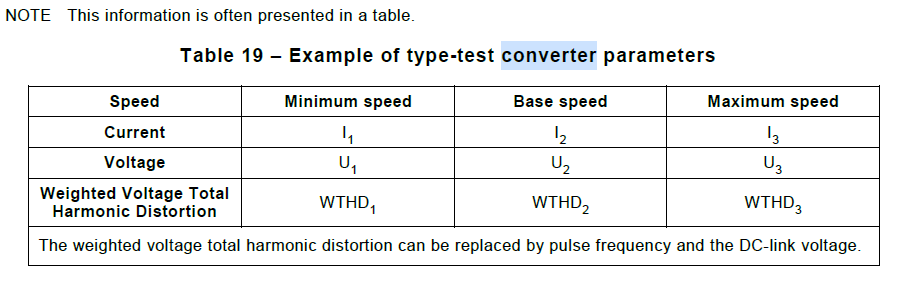
-
Protections provided for motor operation by the converter (if any)
Risk assessment
The parameters and information required for the use of the converter must be stated in the technical file and equipment manual (according to IEC 60079-0:2018, clause 24 and clause 30).
-
The Ex protections provided by the converter must be explained.
-
High-frequency switching in converters can cause stress on the windings and cables, which can create a source of ignition.
-
This condition, as well as an assessment of the risk and relevant necessary precautions (such as the use of a filter at the output of the converter), must be evaluated.
-
Stray currents can occur as a result of converter operation. Some effective ways to reduce the risk include:
-
Using an appropriate filter between the converter and motor.
-
Using shaft earthing or bonding brushes with suitable protection for the intended EPL.
-
Using insulation techniques for the shaft and bearings.
-
A proper earthing system to equalize the potential of the components.
-
Using symmetrically configured low-voltage cables for the connection between the converter and motor.
-
Using a converter with appropriate topology that matches the motor design to minimize common mode voltage.
-
Other methods to reduce common mode voltage and stray currents.
-