Flameproof joints relevant to Exd enclosures
What is a flameproof joint?
A common feature of equipment with Ex d protection type is the presence of flameproof joints.
Explosion-proof enclosures must first be opened to install their relevant inside components and periodically for routine or extraordinary maintenance, so explosion-proof joints are equipped with a door or cover.
Alternatively, there may be moving parts that cut in half or divide the explosion-proof enclosure into two parts, such as the shaft of an electric motor or levers/buttons that activate the opening and closing of switches inside panels.
In both cases described above, the explosion-proof enclosure consists of several components that are assembled and must be able to guarantee the maintenance of Ex d type protection.
The surfaces along which these components are in contact have a certain guaranteed play or distance. In fact, through these distances it must be ensured that any explosion inside the explosion-proof enclosure is not able to ignite the external environment.
Therefore, the corresponding contact surfaces of two parts of a enclosure are defined as an explosion-proof joint, through which the propagation of an explosion within the enclosure to the surrounding explosive environment is stopped.
Example of flue gas outlet from a flange joint of a box with model and size EJB-3

The most common types of explosion-proof joints and their relation to the gas group of explosion-proof equipment
to see the below picture in larger size, click on it.
The most famous explosion-proof joints
-
Cylindrical
-
Threaded
-
Flanged
Explosion-proof jointss are located in the contact surfaces between the bodies and covers, in the threads of the threaded covers, in the cylindrical surfaces of cylindrical joints.
Flanged and cylindrical joints are provided with fixed bolts, while threaded joints are fixed with the same thread that forms the joint.
In the latter case there is a fixed dowel with an anti-loosening function.
As can be seen in the image above, there is a relation between the type of explosion-proof joint and the gas group of the equipment.
Flange joints actually come into crisis when they have to stop the passage of flames of gases such as hydrogen and, most importantly, acetylene.
For this reason, for example, a petroleum product processing site with an environment containing gas group IIC, always requires equipment with explosion-proof threaded or cylindrical joints and, consequently, equipment in round or square enclosures.
Recently, new types of joints have been made with a special mechanical process that allows the creation of rectangular enclosures suitable for the environments containing gas group IIC.
The image above also shows how enclosures with a flat flange joint can be certified for gas group IIB + H2.
In this case, their use is extended to environments with the presence of hydrogen, a situation of no secondary importance if we consider that hydrogen is produced, for example, in the charging points of forklift batteries.
section of a housing with lid equipped with a cylindrical joint and the path followed by the flue gases in red
.jpg)
Flanged explosion-proof coupling of a EJB-3 box in yellow
Principle of operation of flameproof joints
The basic concept of the 'Ex d' type of protection is that an explosion inside the explosion-proof device can occur but is contained without triggering the external gases.
The function of the flame-proof joint is to ensure that the residual gases of the explosion are unable to ignite the atmosphere outside the flameproof enclosure.

By clicking on the image above, you can see it in a larger size.
As shown in figure above, the explosion produces hot gases inside the explosion proof enclosure.
The resulting hot gas jets expand through the lamination joints and their temperature decreases considerably.
During this passage, in fact, the energy released by the explosion is converted into the kinetic energy of the outgoing gases.
For this process to take place as intended, the lengths and tolerances of the joints must be well determined as well as the surface roughness, so that the IEC/EN 60079-1 standard reports specific tables for this purpose.
In flanged joints such as those in Figure above, the flue gases escape for a certain distance from the flat surface of the flange, thus being able to meet rigid obstacles on their path such as support structures, walls, pipes, etc.
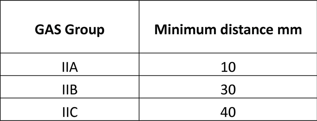
Imposition of a minimum distance between a flat flanged joint and a rigid obstacle depending on the group of gas present at the installation site of the relevant Exd enclosure must be considered in designing the flameproof joints.
Minimum distance between flat joint and rigid obstacles according to table 11 of EN/IEC 60079-1
Another aspect that should be estimated is the tightening torque of the fixing screws of the flanged covers or cylindrical joints.
These screws must be tightened with the correct torque indicated by the manufacturer in the use and maintenance manual.
In fact, when the explosion occurs, the gases escape from all the paths or openings present and the interstices change because of the strong pressures that are exerted on the walls of the enclosure, increasing the passage opening through which the gases escape, as graphically represented in the below figure.
On the other hand, when lids or elements with threaded lamination joints are present, the gas path develops in the spiral of their threading, in this case it is mandatory that the component is fully tightened ensuring at least five threads in contact.